

A three part solution for impact detection and analysis
The Quartix crash detection system is comprised of a sophisticated suite of tools and algorithms which have been developed over the past five years. All of this development has been conducted in-house, based on a huge amount of experience with both real data from the field and crash testing conducted by our R&D teams.
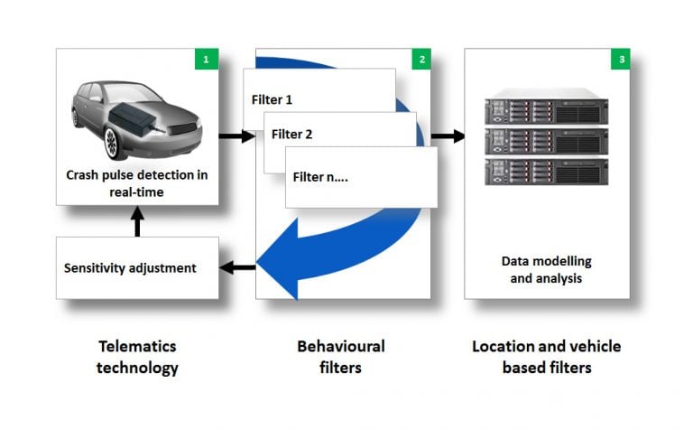
Our unique crash detection system has three key components:
- Telematics technology
- Behavioural filters and data correlation
- Location and vehicle based filters
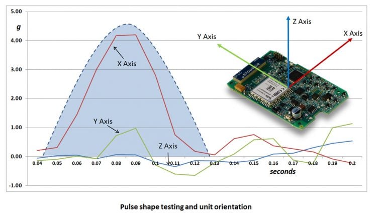
The unit’s orientation is calibrated using Quartix’s proprietary algorithms and crash pulse shapes are examined using mathematical filtering techniques. For more details see the following patent specifications:
(1) unit orientation (2) pulse shape filtering
1. Telematics technology
Both the TCSV11 hard-wired system and the TCSV12 OBD self-install device incorporate a +/-8g 14 bit tri-axis accelerometer which measures the g-forces in each of the three axes 100 times per second.
In addition to the accelerometer, both the TCSV11 hard-wired system and the TCSV12 OBD self-install device monitor speed, location, and heading at a rate of 10 times per second, providing an invaluable means of correlating deceleration measurement between the two methods, hence helping to eliminate false alerts.
The key elements of the telematics part of the solution used in detecting crashes are:
- Orientation of the device is calibrated to ensure that the measurements are lined up with the vertical, side and front/back axes.
- Effects of gravity are removed from accelerometer readings, using Gram-Schmidt orthogonalisation.
- Resultant separated components are tested against pre-set thresholds tailored to that tracking system installation.
- The pulse shape is tested using a finite impulse response filter for elimination of high-frequency vibrations which are unlikely to be caused by an accident.
- The alert is passed to our real-time communications servers, complete with all acceleration, fast GPS, and other data, if criteria are satisfied.
Each telematics system is adjusted overnight, each night, based on its frequency of alert generation. This is carried out by an application on each of our communications servers. Telematics systems generating high number of alerts are adjusted in terms of:
- Crash shape filter criteria
- The minimum horizontal plane impact level threshold
These criteria are used to control the number of false alerts generated by noisy vehicles (e.g. where there is lowered suspension or low-profile tyres), but not to carry out definitive crash detection or filtering.
2. Behavioural filters and data correlation
Tens of thousands of alerts are passed through sets of filters on our communications servers each day. These filters are looking at behaviour in the time leading up to and following the alert, which would be typical of behaviour in the case of an accident, and for data from both the fast (10Hz) GPS chipset, which would correlate with the data recorded by the accelerometer at 100Hz.
There are approximately 40 of these filter sets, each of which is testing around 20 pieces of data. Every one of these filters is tested against each incoming alert on 15s intervals, up to a maximum of seven minutes, to see if there is a match. A few examples of the data which is tested are:
- The position of the vehicle at various intervals after the alert, relative to the location of the alert.
- Whether the ignition has been turned off and, if so, at what time and distance from the alert.
- Speed deltas and speed delta patterns recorded at various key points surrounding the alert .
- The degree of correlation between accelerometer and fast GPS data.
- A range of other relevant criteria, some of which are the result of mathematical modelling of false alert data.
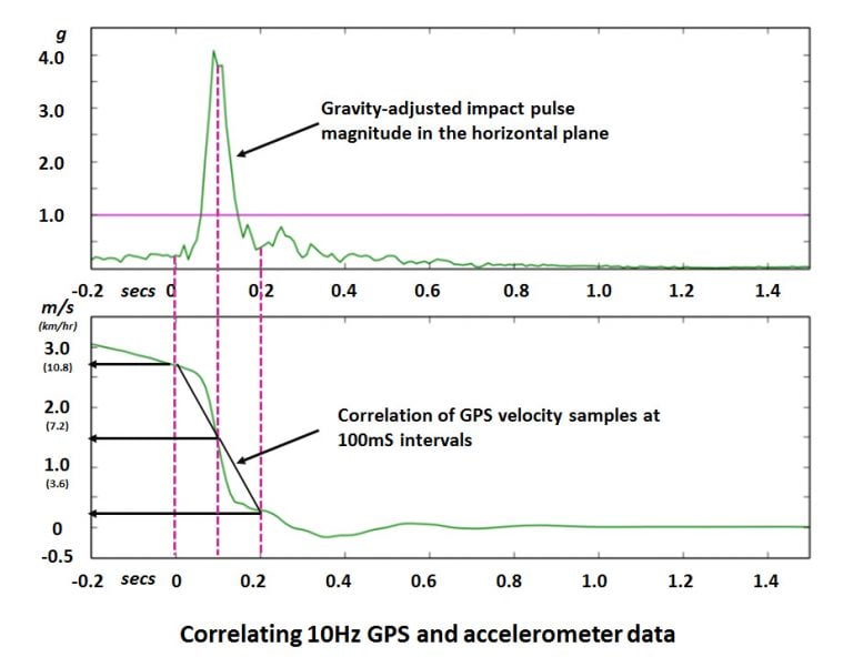
The ability to correlate 10Hz velocity data from the GPS receiver with the accelerometer crash pulse is one of the outstanding insurance telematics features of Quartix’s TCSV11 hard-wired system and TCSV12 OBD self-install device.
Our databases model the typical behaviour of each vehicle and driver, helping to avoid the generation of false alerts caused by frequent use of damaged roads, or parking on the kerb, for example.
3. Location and vehicle based filters
Alerts which pass the filtering tests described above (which would have typically been through a 200:1 selection process) are then processed by SQL database filters which use historic information for the particular vehicle and tracking system in the following ways:
- A search is performed to see if that vehicle has previously recorded a false alert under similar circumstances before.
- A comparison is made between the level of impact in the horizontal plane and the full distribution of alerts recorded by the telematics system in that vehicle.
In essence, these filters are using previously recorded and modelled behaviour of the vehicle and its tracking system to help to distinguish true alerts, on the basis that these would exhibit characteristics which are unusual for that vehicle. These filters continue to learn and adapt, based on data received from the system.
Dealing with false alerts
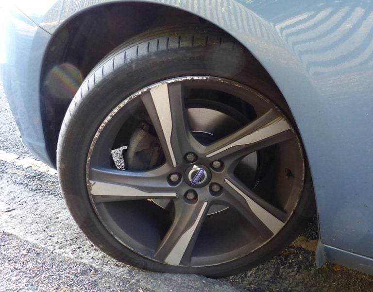
All vehicles are subject to shock and vibration in the course of every day. A few of the potential causes of false alerts are:
- Speed bumps
- Rough roads and pot-holes
- Parking on the kerb
- Doors or boot lid being slammed
- Vehicle environments with high levels of mechanical vibration
Any of these shocks can be picked up by the accelerometer in the telematics system, generating huge numbers of false alerts if sophisticated detection algorithms are not used.
Pot holes and kerbs can lead to significant levels of false alerts, particularly in vehicles with worn or modified suspension. Both the TCSV11 hard-wired system and the TCSV12 OBD self-install device’s calibration and filtering are purpose designed to reduce the number of false alerts.
Crash alert and analysis service
Automated alerts
Alerts which pass through the three parts of the filtering systems described above are provided automatically, either by email or by direct connection through a web-service.
Email alerts provided by our system incorporate direct links to our portal, which displays detailed journey and accident data related to the alert. This information is available in tabular format and is also shown on Google Maps.
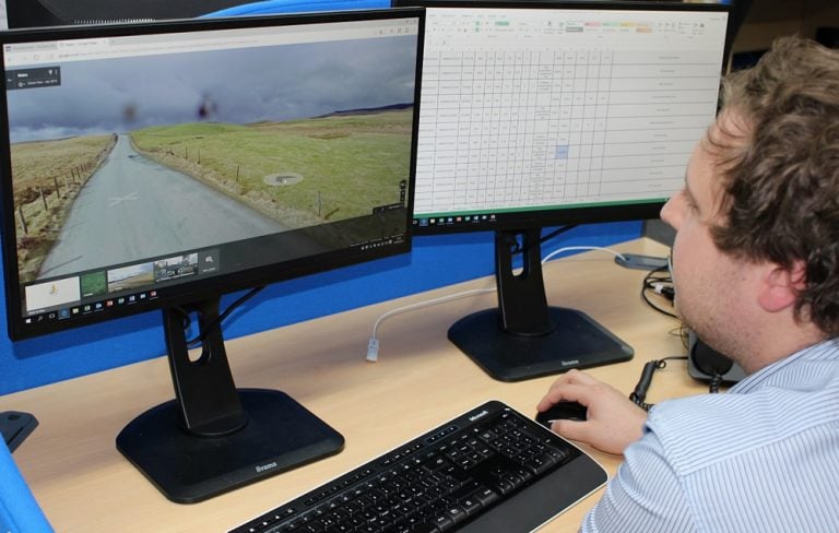
Analysis service
As part of the service we provide for our insurance customers, our trained analysts provide descriptive information concerning the accident, particularly highlighting incidents which appear to have been more serious. This helps our insurance clients prioritise incidents which are more likely to give rise to a larger claim.